Calculation record. S14 seating standard, version 0
Not a pin. A short, thick boss.
The minimum joint in wax was found by calculation, not by faith. Pull the tip sideways: colour shows stress from the cantilever formula, and above 0.40 MPa the part cracks.
Nothing has been physically cast or burned. Everything here is calculated on meshes. Assembly force, wear and elastic modulus are our estimates, and they are labelled as such. Only experiments can answer.
To the verdict: what was chosen and why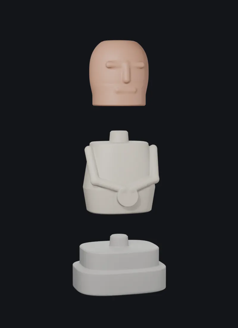
Pull sideways
Bend shown ×200. E = 100 MPa, estimate
σ = 32 · F · L / (π · d³) = 32 · 3.0 · 8 / (π · 14³) = 0.09 MPa
- Breaks from
- 13.5 N
- Force margin
- 10.5 N
- σ at 3 N
- 0.09
- σ at 10 N
- 0.30
- Survives 5 assemblies
- 99.4 %
- Survives 20 assemblies
- 97.6 %
- True deflection, µm
- 2.7
Threshold 0.40 MPa = low strength 0.8 MPa × factor 0.5 for notch and bubble (estimate)
3 N careful, 10 N sharp: force when assembly misses the socket, our estimate, no source
Torso A of the stone idol prototype, our own geometry, a seating check and not a design. The boss is rebuilt to S14 dimensions. The map covers the boss only: the body is not calculated.
The scene did not load, but the calculation works: sliders drive the numbers and the stress plot.
Clearance between castings: 40,000 trials in your browser
Boss and socket shrink together, so only the difference between castings matters. Each point is one pair. We are looking for jamming and slack. A Worker calculates, the GPU draws; the same trials travel when you flip a switch.
Clearance on diameter, mm
Wax lot
Cycles
Clearance on the mould, mm
| Here | Report | |
|---|---|---|
| Clearance 1 %, mm | 0.24 | 0.24 |
| Median, mm | 0.48 | 0.48 |
| Clearance 99 %, mm | 0.73 | 0.73 |
| Jams | 0.00 % | 0.00 % |
| Over 0.8 mm | 0.07 % | 0.07 % |
Slack does not tip the stack: the flat ring carries the load, the boss only centres. A 0.88 mm clearance shifts the part by ±0.44 mm. Tilt comes from an uneven end face, so the face is levelled on a hot plate.
Shrink scatter ±0.5 % within one lot (estimate), ±1.3 % between any lots (from the 2.7–5.3 % range), master ±0.1 mm, trim ±0.05 mm, wear 0.01 mm per side per cycle (estimate). The socket shrinks like a part: an assumption the experiment will test.
What survives 5 and 20 assemblies
Miss force is lognormal and the share of misses is set. Both are our estimates, so the model compares sizes and does not promise service life. Change the assumptions yourself: the order of sizes stays.
You changed an estimate: the numbers below are no longer the report's
Height L = 8 mm comes from the bench. Circles are points from the report table. A thin pin flattens at 33 %: that is not strength but a limit of the model, since misses occur only in some cycles.
Design space: breaking force, N
Tap a cell and the bench rebuilds.
| Ø \ L, mm | 6 | 8 | 10 | 12 |
|---|---|---|---|---|
| 4 | ||||
| 5 | ||||
| 6 | ||||
| 8 | ||||
| 10 | ||||
| 12 | ||||
| 14 | ||||
| 16 |
- ● takes 10 N
- ◐ 3 N only
- ○ breaks even at 3 N
Report table
| Boss, mm | Breaks from, N | 5 assemblies | 20 assemblies |
|---|---|---|---|
| Ø5×8 | 0.6 | 32.9 % | 1.2 % |
| Ø6×8 | 1.1 | 34.5 % | 1.4 % |
| Ø8×8 | 2.5 | 51.8 % | 7.2 % |
| Ø8×6 | 3.4 | 64.0 % | 16.8 % |
| Ø10×8 | 4.9 | 81.0 % | 43.1 % |
| Ø10×6 | 6.5 | 90.7 % | 67.6 % |
| Ø12×8 | 8.5 | 95.9 % | 84.6 % |
| Ø12×6 | 11.3 | 98.7 % | 94.7 % |
| Ø14×8 | 13.5 | 99.4 % | 97.6 % |
| Ø14×6 | 18.0 | 99.9 % | 99.4 % |
| Ø16×8 | 20.1 | 99.9 % | 99.7 % |
Interference flows away
A press fit looks like the obvious answer. Mancktelow's creep law (1988, paraffin 50–52 °C) says otherwise: at 0.3 MPa and 22 °C, 1 % strain is gone in 1.1 h. An interference of 0.1 mm on Ø12 is about that same 1 %.
Stress, MPa
- Until 1 % strain
- 1.1 h
- Interference left, %
- –
- Rate, 1/s
- –
- Measurement
- extrapolation, order of magnitude
Time to 1 % strain
| MPa \ °C | 22 | 25 | 30 | 35 |
|---|---|---|---|---|
| 0.02 | 775 h | 88 h | 2.6 h | 5 min |
| 0.05 | 84 h | 9.6 h | 17 min | 33 s |
| 0.1 | 16 h | 1.8 h | 3.1 min | 6 s |
| 0.3 | 1.1 h | 7.5 min | 13 s | <1 s |
Measured at 24–27 °C from 0.12 MPa and at 35 °C from 0.013 MPa. Lower stress and 22 °C are extrapolation. A different wax: no figures found for candle paraffin. The model is simplified: σ is held constant, while in reality it falls with the interference.
The ring under a 100 g part carries 0.00123 MPa, and creep does not threaten it. The fit does not hold anything: the part stands by its own weight.
Verdict
- Ø12×6 is enough for 5 assemblies (98.7 %), Ø14×6 for 20 assemblies (99.4 %). A Ø6×8 pin survives 5 assemblies in 34.5 % of cases and 20 in 1.4 %.
- The prototypes use S14, Ø14×8: 2 mm longer for lead-in, even though Ø14×6 is stronger by this calculation (18.0 N against 13.5 N). Experiment 1 decides which stays.
- A 0.5 mm clearance on the mould: jamming 0 % within one lot and 0.13 % between lots, median 0.48 mm. After 20 cycles the median is 0.88 mm and 76.5 % of pairs exceed 0.8 mm: a loose fit, but it carries nothing anyway.
- The part holds by its own weight. A press fit does not work: creep removes it in about an hour at 22 °C.
- Ship disassembled only: a 3 g knock (estimate) from a 100 g part gives 0.44 MPa in a Ø14 boss, above the 0.40 MPa threshold. Do not lift an assembled stack by the top.
Where each number comes from
| Quantity | Value | Status |
|---|---|---|
| Paraffin strength | 0.8–2.1 MPa | Engine, audit, review |
| Notch factor | 0.5 | Estimate, no source |
| Side force | 3 and 10 N | Estimate, to measure with a force gauge |
| Share of misses, median force | 20 %, 3 N | Estimate |
| Linear shrink | 2.7–5.3 % | From 8–15 % by volume |
| Scatter within a lot | ±0.5 % | Estimate |
| Master, trim | ±0.1 and ±0.05 mm | Estimate |
| Wear per cycle | 0.01 mm per side | Estimate, experiment 1 measures it |
| Elastic modulus | 100 MPa | Estimate, not found in sources |
| Creep | Power law | Measured on another wax, extrapolated below range |
The cheapest experiments, after the base casting
- Break and 20 cyclesOne mould: bosses Ø8, 10, 12, 14, five of each, plus sockets. Kitchen scale, caliper.Breaking force instead of an estimate, wear per cycle, whether Ø14×6 will do.
- Heat and creepAn S14 pair from the first experiment, 35 °C, a day under weight.Whether the part welds itself in storage.
- Socket coreThe same mould, 3 castings with a silicone core.Cracks around the socket, socket shrink against boss shrink.
What is not here
- Not one casting, break or bench measurement: this is a concept and a calculation.
- The map has no stress concentrator: it is a cantilever, with the margin set by the 0.5 factor.
- Fatigue and wear are not in the survival curves; wear appears in clearances only.
- This page sells nothing and collects no data.
How it is built
- Bench: the real torso mesh from the prototype, a boss built on the S14 profile, a vertex shader bends it as a cantilever, a fragment shader computes σ at every point.
- Clearances: a port of fit_mc in a Worker, 40,000 pairs, points on the GPU.
- The page's formulas are checked against the report tables at every build; any mismatch stops the build.